Hey all, ok so today I thought I would break out the Raspberry Pi and my IoT sensor kit and breadboard. I’m starting to delve into configuring my own sensors and electronics to help me learn Python as well as look into how I can create an Azure IOT Hub and send/receive signals using Azure to act on IoT Devices.
There are a number of components needed to make this work, but at a high level these are:
A Raspberry Pi – I use a Pi 4B from Labists but you can use whichever model you have available.
I wont break down installing a an OS on the Pi4, but once you have Raspion (Raspberry Pi OS Linux build) installed on your Pi then we can go ahead and configure a few settings to allow us to access the RaspPi.


Preparation
In order to use the Raspberry Pi GPIO Extension board for wiring up the components (I bought my kit of Amazon here) we first need to update and install some packages on our Pi, so using your favourite code editor (VSCode for me):
ssh pi@172.20.10.12
pi@172.20.10.12's password:
Linux raspberrypi 5.4.72-v7l+ #1356 SMP Thu Oct 22 13:57:51 BST 2020 armv7l
The programs included with the Debian GNU/Linux system are free software;
the exact distribution terms for each program are described in the
individual files in /usr/share/doc/*/copyright.
Debian GNU/Linux comes with ABSOLUTELY NO WARRANTY, to the extent
permitted by applicable law.
Last login: Fri Oct 30 10:59:01 2020
Then we can run the package updates and install WiringPi library:
sudo apt-get update
sudo apt-get upgrade
sudo apt-get install wiringpi
gpio -v
gpio version: 2.52
Copyright (c) 2012-2018 Gordon Henderson
This is free software with ABSOLUTELY NO WARRANTY.
For details type: gpio -warranty
Raspberry Pi Details:
  Type: Pi 4B, Revision: 02, Memory: 4096MB, Maker: Sony
  * Device tree is enabled.
  *--> Raspberry Pi 4 Model B Rev 1.2
  * This Raspberry Pi supports user-level GPIO access.
Wiring Up our breadboard
The next step of our journey is to wire up our bread board and connect it to our Raspberry Pi using the GPIO (General Purpose In/Out) Extension Board:


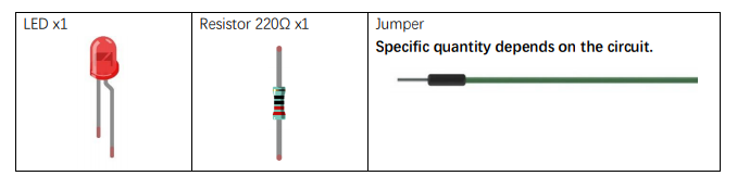
Components needed:
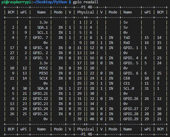
Just a quick check to see the correlation with physical pin numbers with WiringPi Pin numbers we can run the following command:

As I am using a Raspberry Pi 4, it is advisable to update WiringPi:
wget https://project-downloads.drogon.net/wiringpi-latest.deb
sudo dpkg -i wiringpi-latest.deb
Creating our Python Script to Flash the LED!
With the above wiring configuration in place we can see that the PIN numbers align to the following BCM and Physical PIN Numbers (BCM pins are the ones written on the Extension board).
- BCM – GPOI17
- Physical – 11
So in our script we need to use this PIN and set it High (on) or Low (off).
import RPi.GPIO as GPIO
import time
ledPin = 11    # define ledPin
def setup():
    GPIO.setmode(GPIO.BOARD)       # use PHYSICAL GPIO Numbering
    GPIO.setup(ledPin, GPIO.OUT)   # set the ledPin to OUTPUT mode
    GPIO.output(ledPin, GPIO.LOW)  # make ledPin output LOW level
    print ('using pin%d'%ledPin)
def loop():
    while True:
        GPIO.output(ledPin, GPIO.HIGH)  # make ledPin output HIGH level to turn on led
        print ('led turned on >>>')     # print information on terminal
        time.sleep(1)                   # Wait for 1 second
        GPIO.output(ledPin, GPIO.LOW)   # make ledPin output LOW level to turn off led
        print ('led turned off <<<')
        time.sleep(1)                   # Wait for 1 second
def destroy():
    GPIO.cleanup()                      # Release all GPIO
if __name__ == '__main__':    # Program entrance
    print ('Program is starting ... \n')
    setup()
    try:
        loop()
    except KeyboardInterrupt:   # Press ctrl-c to end the program.
        destroy()
We can see in the code we have defined 3 funcitons:
- setup()
- loop()
- destroy()
The main code of our script looks to run the loop() function which sets our GPIO Pin 11 to High and Low with a 1 second timer in between.
So, lets get the script saved on the Pi and run it!
I have saved a copy of my python script here:

lets run it:
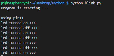
So there we have it! My first python script to control GPIO across a raspberry Pi
Next step is to integrate this with Azure IoT hub!!
100DaysOfCloud Overview
My Main ReadMe Page is all set up with a bit about me!

The guys at 100DaysofCloud have set up the GitHub repo to be cloned and also have a great repo containing ideas and areas to collaborate on: https://github.com/100DaysOfCloud/100DaysOfCloudIdeas
My Github Journey tracker can be found here: https://github.com/jonnychipz/100DaysOfCloud
Please Watch/Star my repo and feel free to comment of contribute to anything I push! I really look forward to hearing from anyone who is going to jump on the journey around the same time as me! Lets see where I get to in 100 days!
I would encourage others to jump on this journey, I’m not sure that I will be able to commit every day for 100 days, but as long as I can complete 100 days that will be great!